+86 186 7553 4520
 jiayonghuang03@gmail.com


Single-phase and Three-phase IP PDU Meters for Network Remote Monitoring and Management Power Distribution System

2. Product Introduction
2.2 Function introduction
| Performance parameters | Technical indicators | |||||
| Electrical parameters | Input optional | Single-phase | Input voltage | 176-264V | ||
| Maximum total load current | 63A | |||||
| Three-phase | Input voltage | 3*220V | ||||
| Maximum total load current | 3*63A | |||||
| Output | Output voltage | 176-264V | ||||
| Output current | 8A, optional high current 20A | |||||
| Output port | Optional, magnetic latching relays up to 36 ports. | |||||
| Optional, ordinary relays up to 12 ports. | ||||||
| Frequency | 50Hz or 60Hz | |||||
| User interface | Display screen | TFT color screen | ||||
| Operation buttons | Up, down, setting, reset buttons | |||||
| Communication interface | Ethernet * 1, RS485 * 2 | |||||
| Temperature and humidity interface | 1 port | |||||
| Electrical parameter measurement and control function | Total PDU measurement | Voltage, Current, Power, Power Factor, Energy, Frequency | ||||
| Measurement of each output | Voltage, Current, Power, Power Factor, Energy, Frequency | |||||
| Each output can be remotely turned on/off | Yes | |||||
| Customized power-on/off timing and interval time for each output | Yes | |||||
| Administrator permissions can be defined in different levels. | Yes | |||||
| Customized alarm signal thresholds | Voltage and current are adjustable | |||||
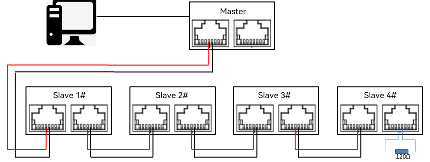
| Cascade function | Yes, 4 meters can be cascaded | |||||
| Monitoring function | Load current monitoring | |||||
| Load power monitoring | ||||||
| Voltage monitoring | ||||||
| Electric energy monitoring | ||||||
| Ambient temperature and humidity monitoring | ||||||
| Setting function | Load current upper and lower limit settings | |||||
| Ambient temperature and humidity upper and lower limit settings | ||||||
| Email alarm address settings | ||||||
| SNMP (V1, V2C) settings | ||||||
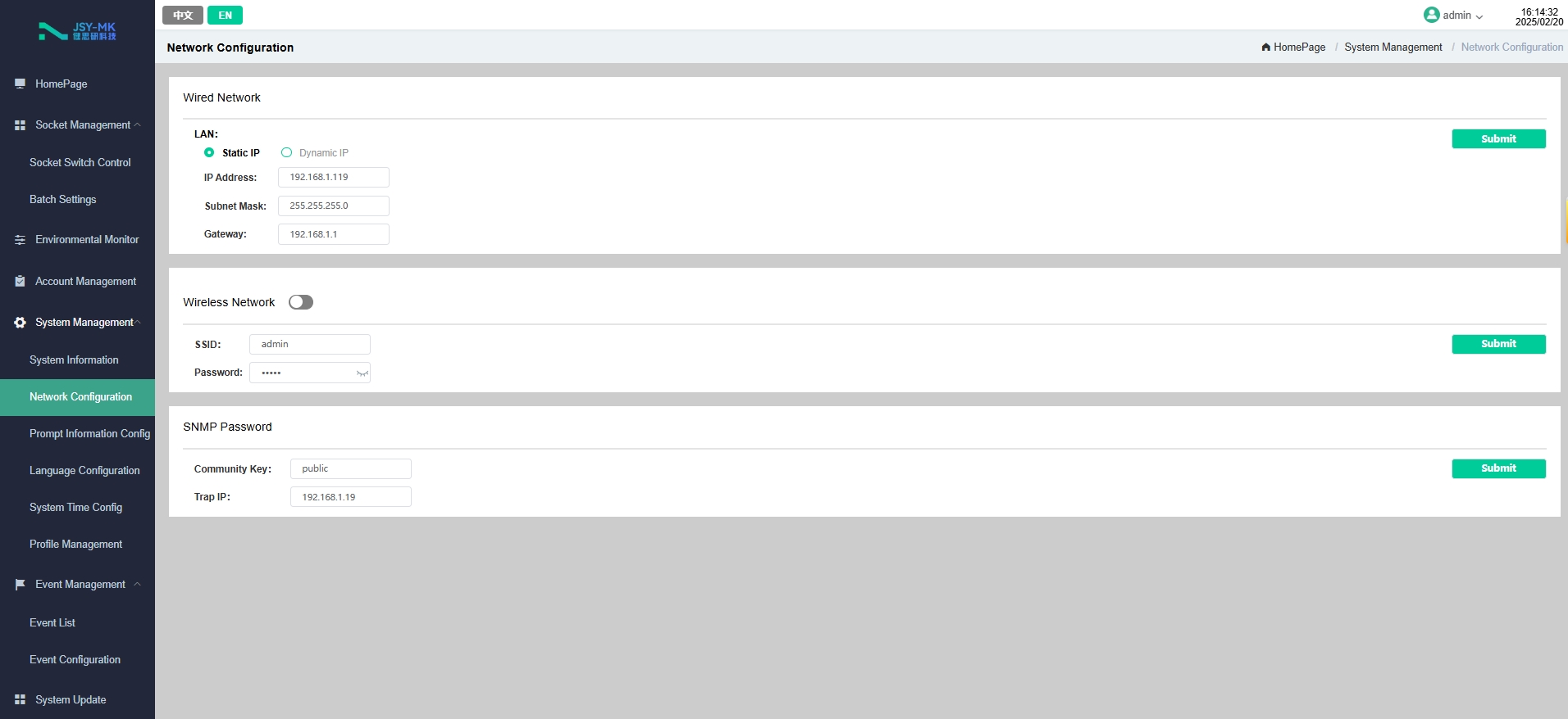
| Network parameter settings (IP, gateway, mask, DNS) | ||||||
| Alarm function | System Alarm | When the load current exceeds the rated value | ||||
| When the temperature and humidity exceed the limit value | ||||||
| Customized Alarm |
When the load current exceeds the rated value | |||||
| When the temperature and humidity exceed the limit value | ||||||
| Alarm method | Buzzer beeps | |||||
| LCD value flashes | ||||||
| Automatically send E-mail to the system administrator | ||||||
| SNMP sends Trap alarm status information | ||||||
| Serial communication background sends alarm status information | ||||||
| Access method | WEB access control through IE | |||||
| SNMP (V1) access control through standard network management workstation | ||||||
| User management | User ID and password settings | |||||
| Environment | Operating temperature | -10~50℃ | ||||
| Extreme operating temperature | -20~60℃ | |||||
| Relative humidity | 10~90% | |||||
| Storage and transportation extreme temperature | -40~70℃ | |||||
2.3 Model selection
3. Main functions
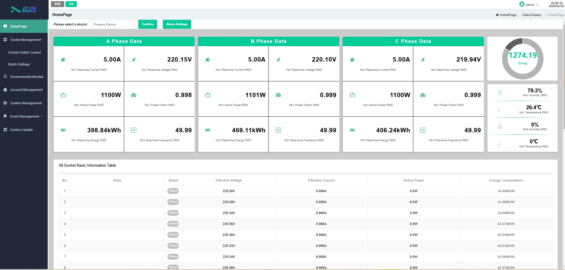
3.1 Real-time monitoring function
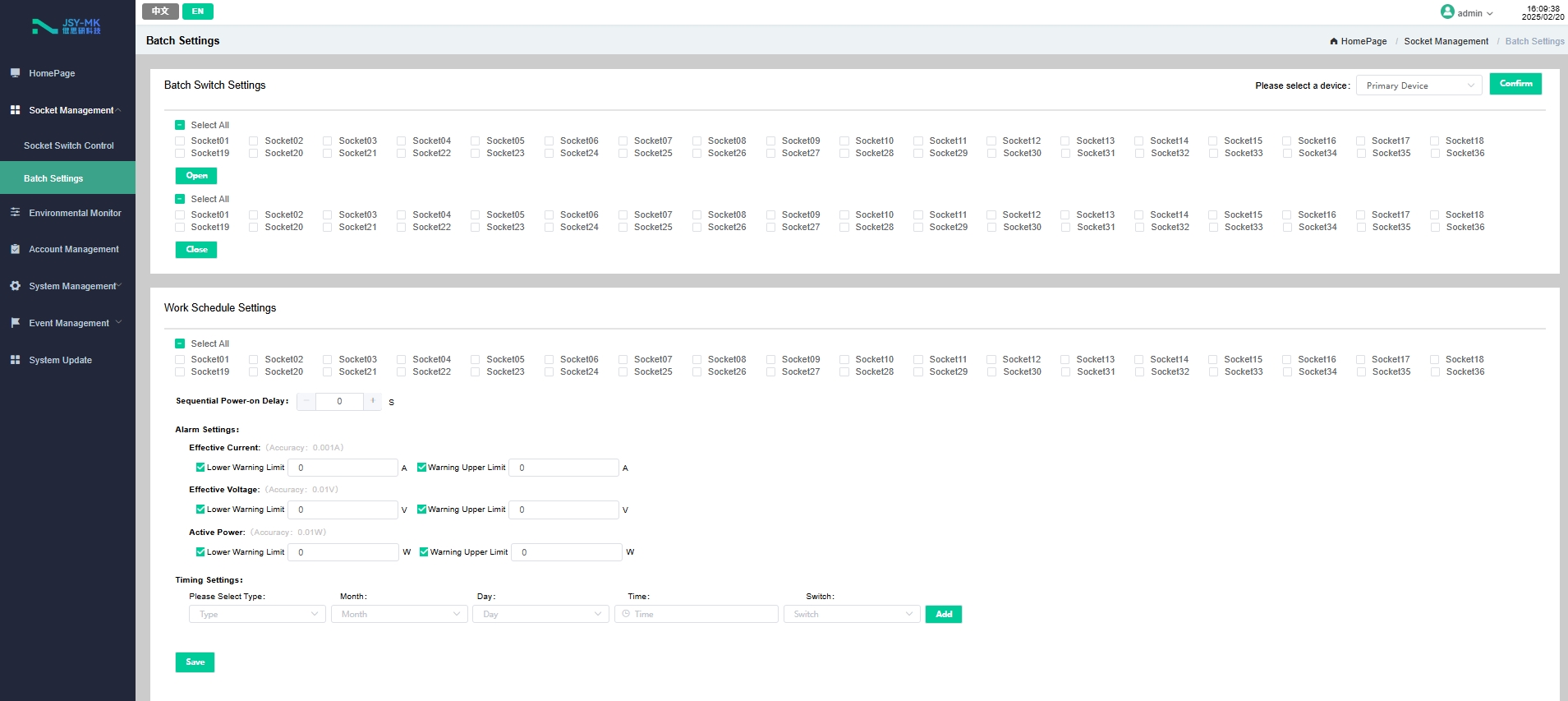
3.2 Socket unit control
3.3 Customized alerts
3.4 Master-slave (cascade) communication
4.1 User interface and parameters

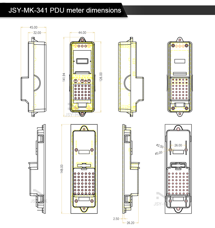
4.2 Product size
JSY-MK-341 IP Intelligent PDU Meter Dimensions.
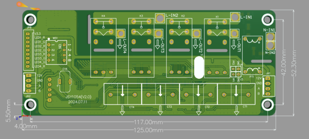
JSY1054 4-channel relay control module dimensions
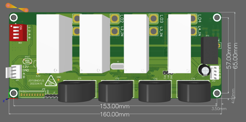
JSY1084 4-channel relay control module dimensions
5. Web Network Operation
5.1 Supported browsers
5.2 Cascade Setting Instructions
5.2.1 Cascade settings
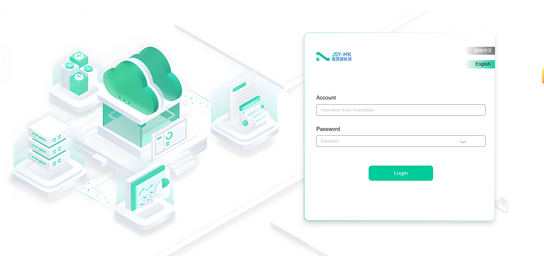
1.1.1 Log in
As shown

The default username and password for the super administrator is: " admin", then click Login. as shown in Figure 5.2.2: