+86 186 7553 4520
 jiayonghuang03@gmail.com


Professional-grade monitoring and management power supply system is the latest scientific research result obtained after years of dedicated research in the field of power distribution technology. This product is based on the development trend of future power distribution monitoring and management technology in the world and combines the technical requirements of modern data center application environment.
Single-phase and three-phase PDU meters are based on the innovative SUM (Sustainable, Upgradable and Maintainable) design concept technology. As a key component of the metered cabinet power distribution unit (PDU), after being installed in the PDU body, it can provide active metering functions . User-set alarm thresholds can issue potential circuit overload warnings through real-time local alarms. Users can configure metered cabinet PDUs via RS485.
Single-phase and three-phase PDU meters are based on the innovative SUM (Sustainable, Upgradable and Maintainable) design concept technology. As a key component of the metered cabinet power distribution unit (PDU), after being installed in the PDU body, it can provide active metering functions . User-set alarm thresholds can issue potential circuit overload warnings through real-time local alarms. Users can configure metered cabinet PDUs via RS485.
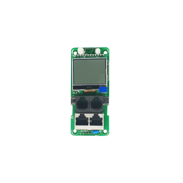
2.1 Function Introduction
|
Performance parameters |
Technical indicators |
|||||
|
Electrical parameters |
Input Optional |
Single Phase |
Input voltage | 176-264V | ||
| Maximum load current | 63A | |||||
|
Three-phase |
Input voltage | 3*220V (Phase A power supply) | ||||
| Maximum load current | 3*63A | |||||
| Frequency | 50/60HZ | |||||
|
User interface |
Display | Black and white dot matrix screen | ||||
| Operation buttons | Up, down, setting, reset button | |||||
| Communication interface | 1-channel RS485( 2 Interfaces) | |||||
| Temperature and humidity interface | 2-channel | |||||
|
Electrical parameter measurement |
PDU measurement | Voltage, current, power, electric energy | ||||
| Customize alarm signal thresholds | Voltage and current adjustable | |||||
|
Monitoring function |
Load current monitoring | |||||
| Load power monitoring | ||||||
| Voltage monitoring | ||||||
| Power consumption monitoring (active power, reactive power) | ||||||
| Ambient temperature and humidity monitoring | ||||||
|
Setting the function |
Load current upper limit setting | |||||
| Voltage upper and lower limit settings | ||||||
| Chinese / English switch | ||||||
|
Alarm function |
System Alarm |
When the load current exceeds the rated value | ||||
|
Custom Alerts |
When the load current exceeds the threshold value | |||||
| When the voltage exceeds the threshold | ||||||
|
Alarm method |
Buzzer beeps | |||||
|
Serial communication function |
Port Definition | Two RJ45 interfaces (RS485 interfaces) are standard | ||||
| Communication Protocol | Default MODBUS RTU protocol | |||||
| Baud rate | Default: 9600bps, configurable 4800, 19200, 38400bps. | |||||
| cascade | Support RS485 cascade | |||||
|
Environment |
Operating temperature | -10 ~ 50℃ | ||||
| Extreme operating temperature | -20 ~ 60℃ | |||||
| Relative humidity | 10 ~ 90% | |||||
| Storage and transportation temperature limit | -30 ~ 70℃ | |||||
2.2 Model selection
◆ JSY1095 represents single-phase RS485 communication PDU meter.
◆ JSY-MK-360 represents three-phase RS485 communication PDU meter.
Functional technical parameters
3.1 Real-time monitoring function
◆ The display screen displays the monitored load current, voltage, power, electric energy, power factor. Temperature/humidity sensor data and operating status.
3.2 Customized Alarms
◆ Load current/voltage over-limit threshold can be customized.
◆ The buzzer sounds.
3.3 Definition of key indicator light
◆ [ Direction Keys ] : Short press the direction keys to cycle through information such as current, temperature and voltage.
◆ [ Settings ] : Press and hold the Setting button for 3 seconds to enter the Setting interface. The system parameters can modify communication parameters, various thresholds, Chinese and English switching and other parameters.
◆ [ Reset button ]: Press it briefly to reset the system .
◆ [ Alarm indicator light ] : It is off under normal circumstances and stays on when there is an alarm signal.
◆ [ Operation indicator ] : After the device is successfully powered on, the operation indicator flashes .
◆ [ Communication indicator light ] : The indicator light flashes when the device is communicating , and the indicator light goes out when there is no communication.
3.4 Terminal Definition
3.4.1 RS485 interface terminal
RS485 interface, Pin4 (blue) 485 A, Pin5 (blue and white) 485 B.
Note: The wiring color of RJ45 may be incorrect, it depends on the actual usage.