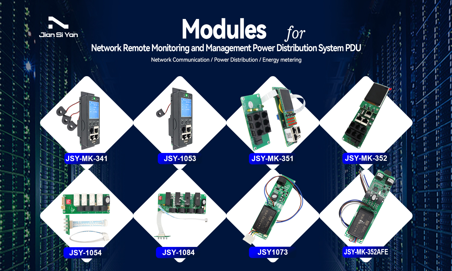
PDU & iPDU Modules for Network Remote Monitoring and Management Power Distribution System PDU
What's IP PDU Meter?
- IP PDU Meter (Intelligent Power Distribution Unit Meter) is an intelligent device that integrates power distribution, monitoring and management, and is designed for data centers, industrial facilities, etc. It remotely monitors current, voltage, power consumption and other data in real time through IP network, supports accurate metering, load control and energy optimization, and provides environmental sensor (temperature and humidity) integration to ensure equipment safety and energy efficiency, and reduce downtime risks.
What is the difference between PDU and IPDU?
- IPDU Per Outlet Monitored & Switched
- However, unlike traditional Power Distribution Units (PDUs), an iPDU goes beyond basicpower delivery by incorporating intelligent features and network connectivity, allowing forreal-time monitoring,management, and control of power consumption.
What are the manufacturers of PDU&IPDU Meter?
- PDU & IPDU Meter Manufacturers
- Global Brands:
- Schneider Electric / Eaton / Vertiv / Raritan / Server Technology (Legrand) / CyberPower / Tripp Lite (Eaton) / APC (Schneider)/ PDU Expert / BayTech
- Chinese Brands:
- Huawei / Delta Electronics / Kehua / Sugon / EAST Group / DPC / LADIS
- 1. JSY-MK PDU & iPDU Meter Introduction
- Professional-grade network remote monitoring and management power distribution system is the latest scientific research achievement in the field of power distribution technology after years of dedicated research. This product is based on the development trend of the world's future power distribution monitoring and management technology, combined with the technical requirements of the modern data center application environment, and adopts the latest core technology with completely independent intellectual property rights, as well as network communication, power distribution, and electric energy metering technologies to design the latest network remote monitoring and management power distributor.
2. JSY-MK PDU & iPDU Meter Overview
- 2.1 Product Overview
- Single-phase and three-phase smart PDU meters are based on the innovative SUM (sustainable, scalable and maintainable) design concept technology. As a key component of the metering cabinet power distribution unit (PDU), after being installed into the main body of the PDU, it can Provides active metering capabilities for energy optimization and circuit protection. User-set alarm thresholds can effectively reduce risks by warning of potential circuit overloads through real-time local and remote alarms. Metered rack PDUs provide power usage data to support data center managers in making informed decisions about load balancing and proper IT sizing, thereby significantly reducing total cost of ownership. Users can configure metered cabinet PDU via Ethernet access or RS485. This series of products can be widely used in data center rooms such as IDC, banks, securities, governments, and enterprises.
2.2 Function introduction
| JSY1053 Single-Phase IP PDU Meter & JSY-MK-341 Three-phase IP PDU Meter | |||||
|
Performance parameters |
Technical indicators |
||||
|
Electrical parameters |
Input optional |
Single-phase |
Input voltage | 176-264V | |
| Maximum total load current | 63A | ||||
|
Three-phase |
Input voltage | 3*220V | |||
| Maximum total load current | 3*63A | ||||
| Output | Output voltage | 176-264V | |||
| Output Current | 8A, optional high current 20A | ||||
| Output Port | Optional, magnetic latching relays up to 36 ports | ||||
| Optional, ordinary relays up to 12 ports | |||||
| Frequency | 50Hz or 60Hz | ||||
|
User interface |
Display screen | TFT color screen | |||
| Operation buttons | Up, down, set, reset buttons | ||||
| Communication interface | Ethernet * 1, RS485 * 2 | ||||
| Temperature and humidity interface | 1 port | ||||
| Electrical parameter measurement and control function | Total PDU measurement | Voltage, current, power, electric energy | |||
| Measurement of each output | Voltage, current, power, electric energy | ||||
| Each output can be remotely turned on/off | Yes | ||||
| Customized power-on/off timing and interval time for each output | Yes | ||||
| Administrator permissions can be defined in different levels. | Yes | ||||
| Customized alarm signal thresholds | Voltage and current are adjustable | ||||
| Cascade function | Yes, 4 meters can be cascaded | ||||
|
Monitoring function |
Load current monitoring | ||||
| Load power monitoring | |||||
| Voltage monitoring | |||||
| Electric energy monitoring | |||||
| Ambient temperature and humidity monitoring | |||||
|
Setting the function |
Load current upper and lower limit settings | ||||
| Ambient temperature and humidity upper and lower limit settings | |||||
| Email alarm address settings | |||||
| SNMP (V1, V2 C ) settings | |||||
| Network parameter settings (IP, gateway, mask, DNS) | |||||
|
Alarm function |
System Alerts |
When the load current exceeds the rated value | |||
| When the temperature and humidity exceed the limit | |||||
| CustomizedAlarm | When the load current exceeds the rated value | ||||
| When the temperature and humidity exceed the limit | |||||
|
Alarm method |
Buzzer beeps | ||||
| LCD value flashes | |||||
| Automatically send E-mail to the system administrator | |||||
| SNMP sends Trap alarm status information | |||||
| Serial communication background sends alarm status information. | |||||
|
Access method |
WEB access control through IE | ||||
| SNMP (V1) access control through standard network management workstation | |||||
|
User Management |
User ID and password settings | ||||
|
Environment |
Operating temperature | -10 ~ 50℃ | |||
| Extreme operating temperature | -20 ~ 60℃ | ||||
| Relative humidity | 10 ~ 90% | ||||
| Storage and transportation extreme temperature | -40 ~ 70℃ | ||||
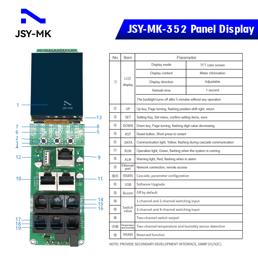
| JSY-MK-352 IP PDU Meter Module | |||||
| Performance parameters | Technical indicators | ||||
| Electrical parameters | Input Optional |
Single Phase | Input voltage | 176-264V | |
| Maximum total load current | 63A | ||||
| Three-phase | Input voltage | 3*220V 50/60HZ | |||
| Maximum total load current | 3*32A Optional 63A, 120A, 150A | ||||
| Output | Output Voltage | 176-264V | |||
| Output Current | 8A, optional high current 20A | ||||
| Output Port | Optional, up to 36 ports | ||||
| Frequency | 50/60Hz | ||||
| User interface | Display | TFT color screen | |||
| Operation buttons | Up, down, set, reset buttons | ||||
| Communication interface | One Ethernet, two RS485 | ||||
| Temperature and humidity interface | Two | ||||
| Switch input interface | Two interfaces, 4 channels | ||||
| Switch output interface | One interface,2 channels | ||||
| Electrical parameter measurement | PDU total measurement | Voltage, current, power, electric energy | |||
| Each output measurement | Voltage, current, power, electric energy | ||||
| Each output can be remotely turned on/off | Yes | ||||
| Customize the power-on/power-off sequence and interval time for each output | Yes | ||||
| Administrator permissions can be defined in different levels | Yes | ||||
| Customize alarm signal thresholds | Voltage and current adjustable | ||||
| Cascade function | Yes, 4 products can be cascaded | ||||
| Monitoring function | Load current monitoring | ||||
| Load power monitoring | |||||
| Voltage monitoring | |||||
| Power monitoring | |||||
| Ambient temperature and humidity monitoring | |||||
| Setting the function | Load current upper and lower limit settings | ||||
| Ambient temperature and humidity upper and lower limit settings | |||||
| Email alert address settings | |||||
| SNMP (V1, V2c,V3) settings | |||||
| Network parameter settings (IP, gateway, mask, DNS ) | |||||
| Alarm function | system Alerts |
When the load current exceeds the rated value | |||
| When the temperature and humidity exceed the limit | |||||
| Custom Alerts |
When the load current exceeds the rated value | ||||
| When the temperature and humidity exceed the limit | |||||
| Alerts Way |
Buzzer beeps | ||||
| LCD value flashes | |||||
| Automatically send an email to the system administrator | |||||
| SNMP sends Trap alarm status information | |||||
| Serial communication background sends alarm status information | |||||
2.3 Model selection
1) Solution 1
- PDU module(1U Size with shell/housing) are divided into two parts
- ① PDU Meter(built-in power module)
- ② Relay control module
- Models selection can refer to the following:
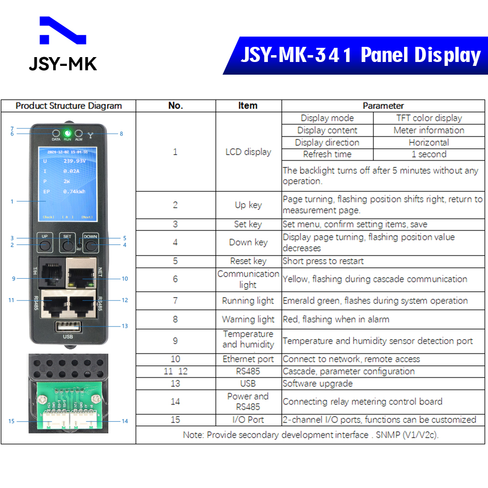
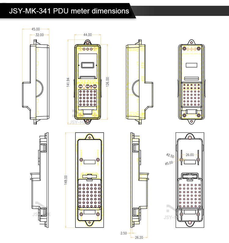
- ③ JSY-MK-341 Three-phase IP PDU Meter
- ④ JSY1053 Single-phase IP PDU Meter
- ⑤ JSY-MK-360 Three-phase RS485 PDU Meter
- ⑥ JSY1095 Single-phase RS485 PDU Meter
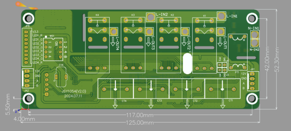
- ⑦ JSY1054 Relay control module (up to 16A)
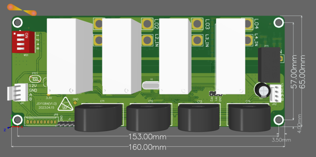
- ⑧ JSY1084 Relay control module (up to 50A)
2) Solution 2
PDU modules(without shell/housing) are divided into three major parts
- ① PDU Main borard
- ② Power module (Single-phase or Three-phase)
- ③ Relay control module
- Models selection can refer to the following:
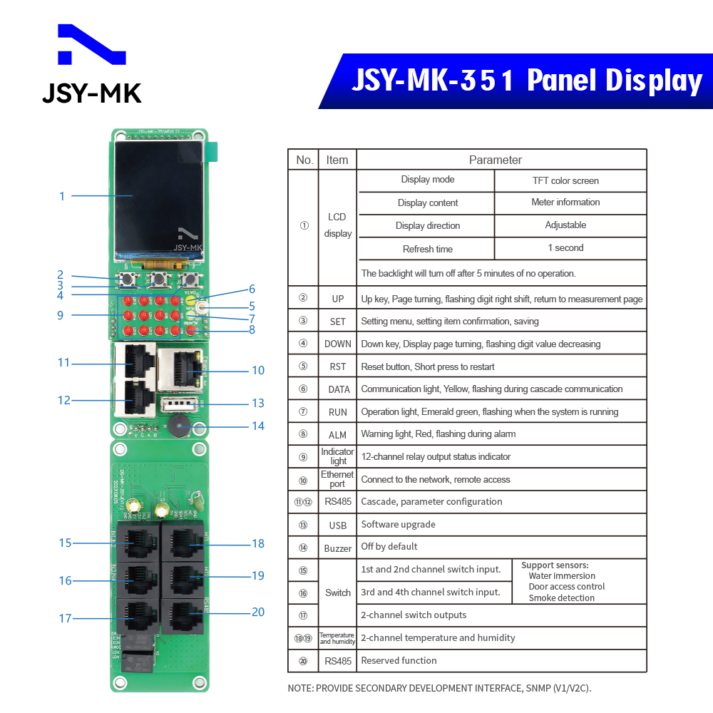
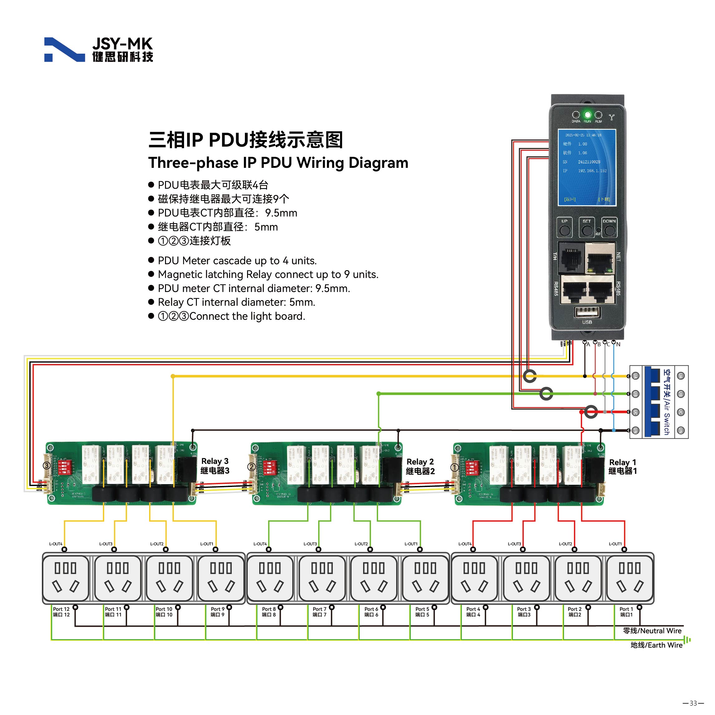
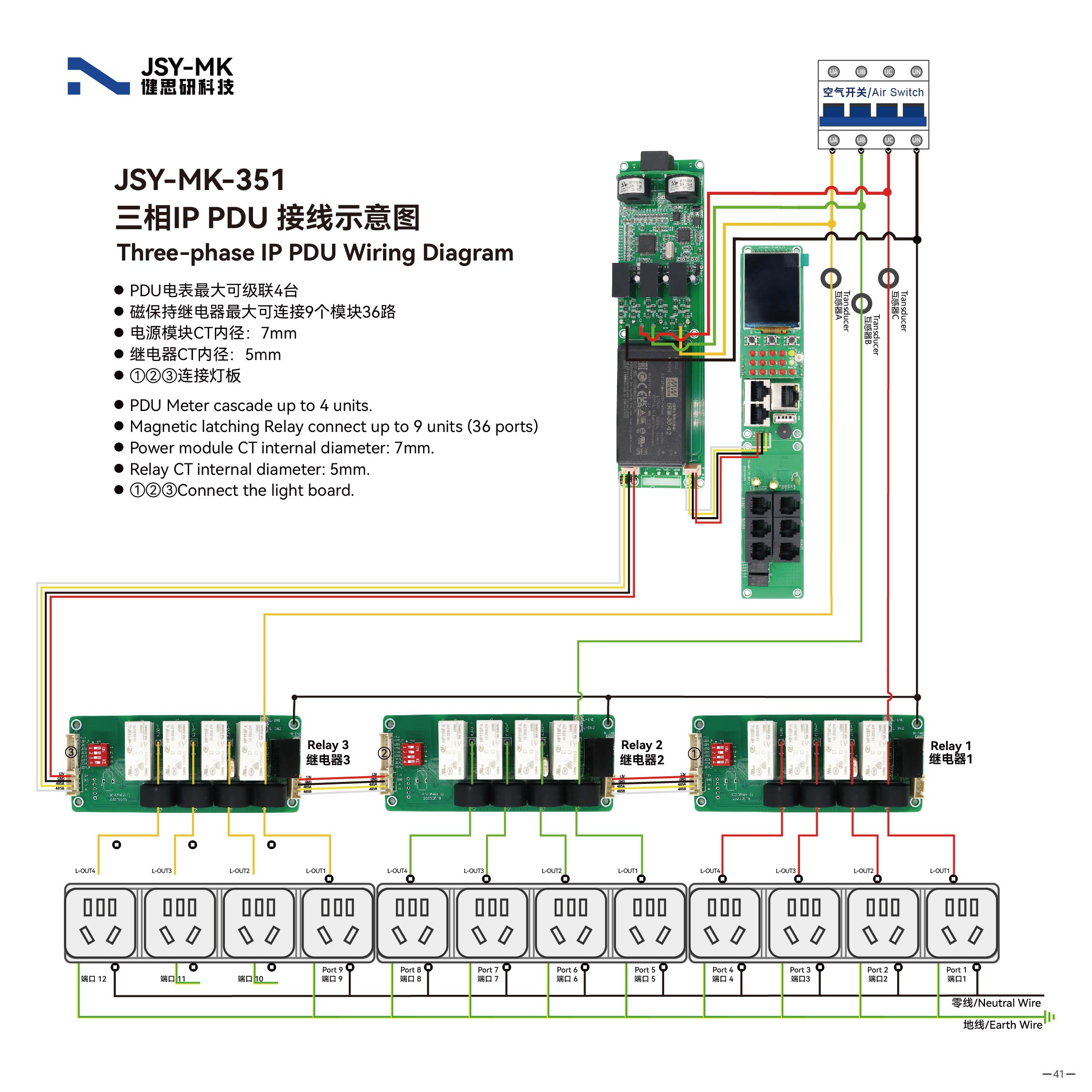
- ④ JSY-MK-351 PDU Main borard
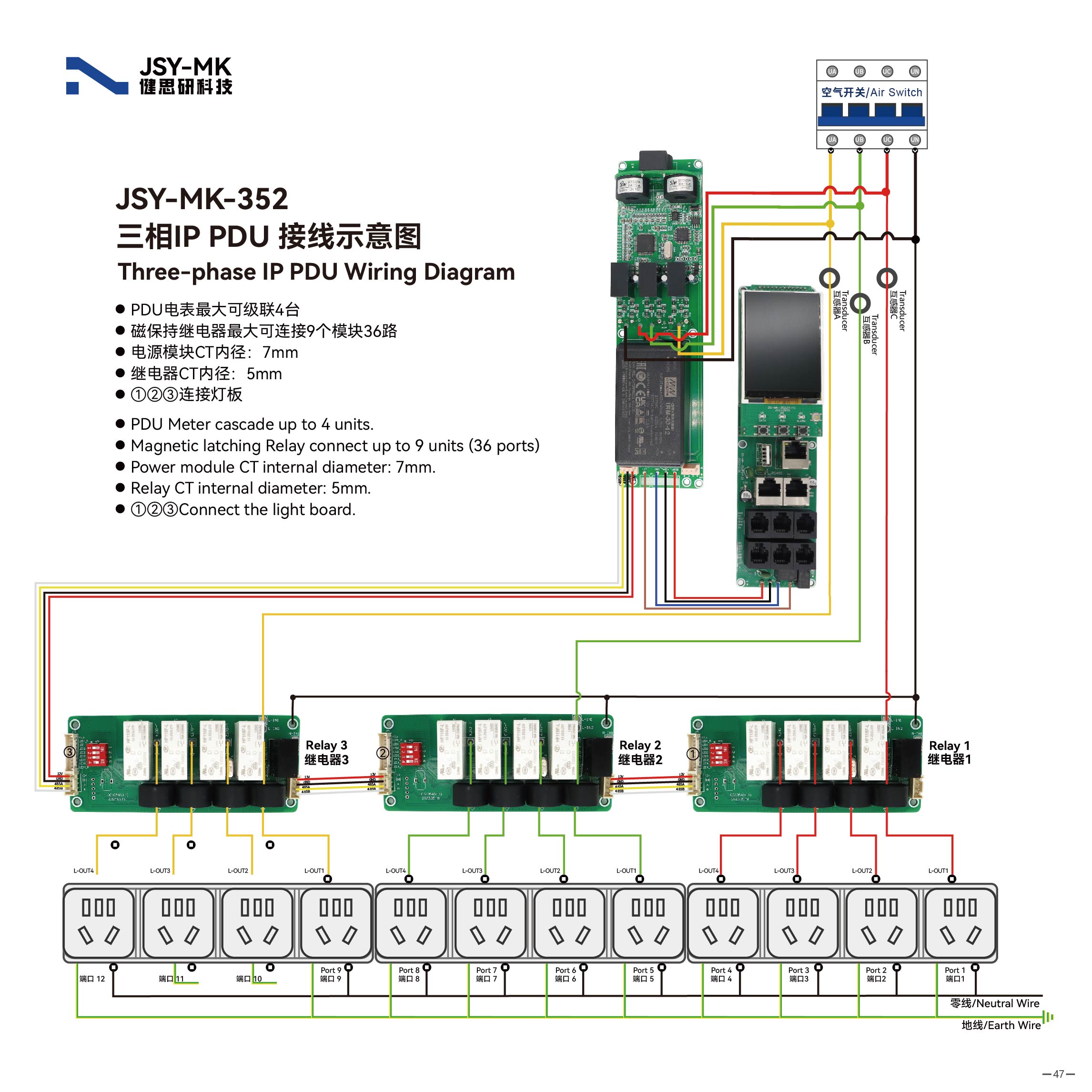
- ⑤ JSY-MK-352 PDU Main borard
- ⑥ JSY-MK-352AFE Three-phase Power module
- ⑦ JSY1073 Single-phase Power module
- ⑧ JSY1054 Relay control module (up to 16A)
- ⑨ JSY1084 Relay control module (up to 50A)
- [The Meter or mainboard can cascade up to 4 slaves, and the relay can connect up to 9pcs/36 ports]
3. Main functions
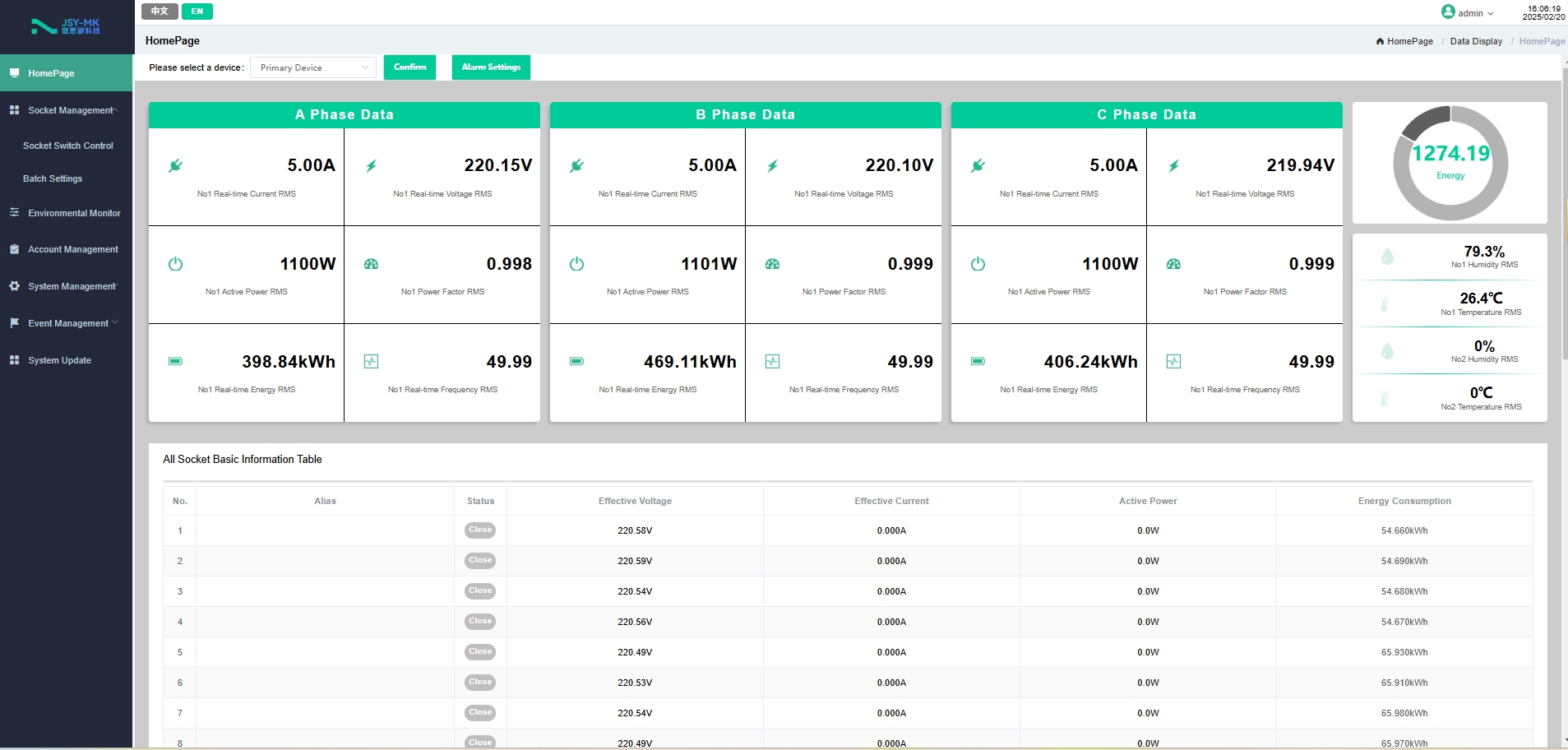
3.1 Real-time monitoring function
- The display screen can view the monitored total load current, total voltage, total power, total electric energy, power factor, and load current parameters of each independent unit: the content displayed on the LCD screen can be viewed on the Web page, and the closed/open state of each independent unit, temperature/humidity sensor data and operating status can be controlled. 2-channel I/O ports, functions can be customized.
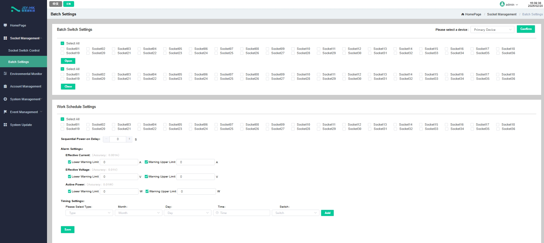
3.2 Socket unit control
- ◆ Control the closing and opening of a single relay, or control multiple relays simultaneously.
- ◆ You can set the sequential delay power-on, up to 6 seconds. (This means that when two or more channels are controlled continuously, after the previous channel is completed, you need to wait 6 seconds before the next channel starts to operate.)
- ◆ Each relay can be set to start at a fixed time .
3.3 Customized alerts
-
◆ The total load current/voltage over-limit threshold can be customized, the load current over-limit threshold of each socket unit can be customized, and the temperature/humidity over-limit threshold can be customized.
- ◆ The buzzer sounds. an email is sent to the system administrator. SNMP sends a trap alarm status information.
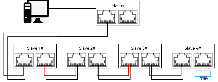
3.4 Master-slave (cascade) communication
- The two interfaces are the same RS485 communication bus, providing two interfaces for easy cascading. RS485 communication cascade can connect up to 4 instruments. Communication cables can use ordinary shielded twisted pair cables. When RS485 communication cables are routed outdoors, attention should be paid to grounding the cable shielding layer. The total length of the communication cable should not exceed 1200 meters. The positive and negative polarities of the RS-485 ports of each device must be connected correctly. If the shielded twisted pair cable is long, it is recommended to connect a 120 Ω resistor at the end and reduce the transmission rate to improve the reliability of communication.
- 4. Technical parameters and installation
4.1 User interface and parameters
4.2 Product size
5. Web Network Operation
5.1 Supported browsers
- You can access the PDU through its web interface using IE, Google 360, or Microsoft Edge . Other commonly used browsers may work but have not been fully tested.
5.2 Cascade Setting Instructions
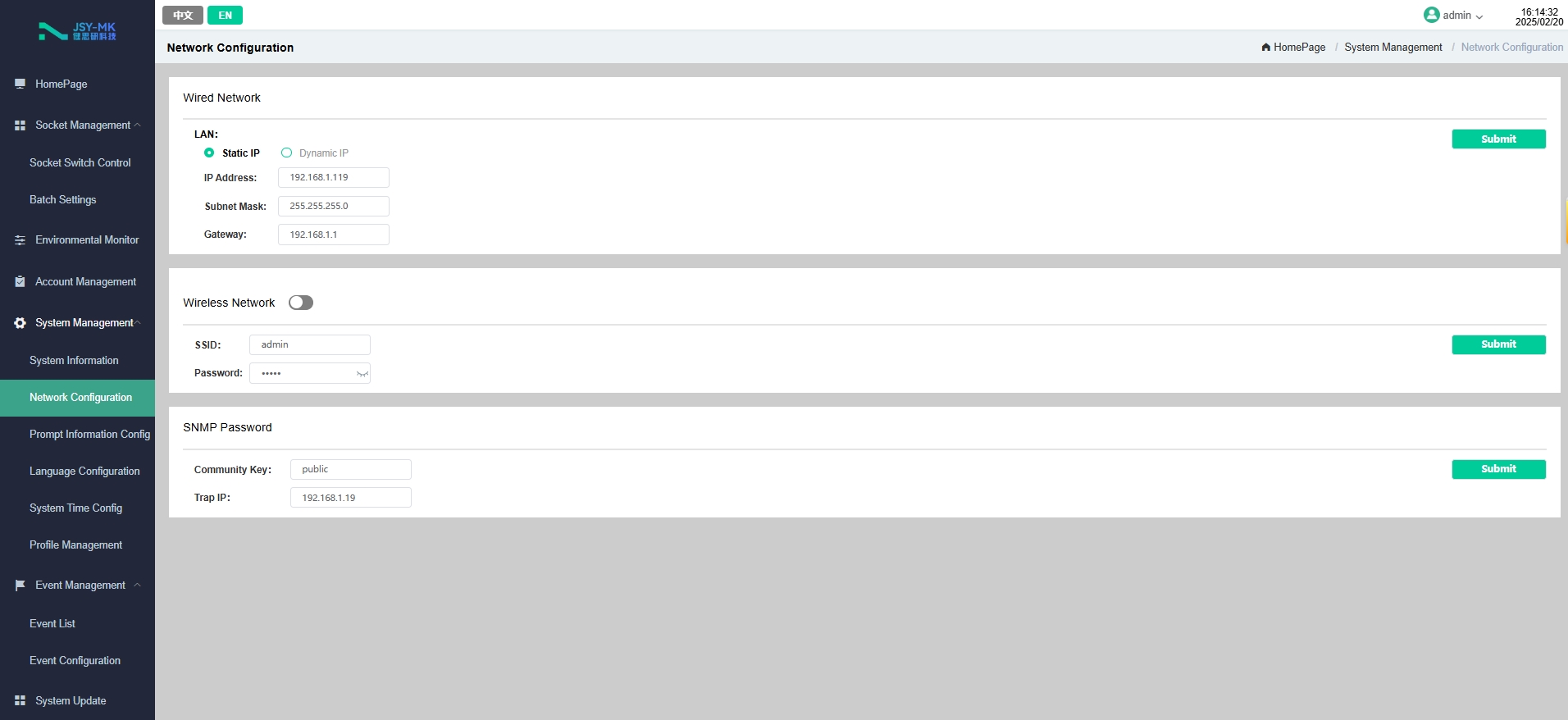
- ◆ You can use the PDU's system IP address as the URL of the web interface and log in using a case-sensitive username and password.
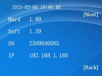
- ◆ The PDU uses a static IP address by default when it leaves the factory. The default address is 192.168.1.192. The current IP address can be queried from the network status page on the LCD display of the display module. If you need to configure a dynamic IP, you need to enable the DHCP function of the device.
- ◆ Before using the cascading function, you need to select the master-slave mode for each PDU configuration. The master mode has only one PDU, and the slave mode can be configured with 4 PDUs by default .
5.2.1 Cascade settings
- After the PDU is powered on, plug the network cable into its network port. At this time, in the LCD display of the display module, by short pressing the button, you can query the IP address from the host information, as shown in Figure 5.2.1 : 192.168. 1 .1 92.
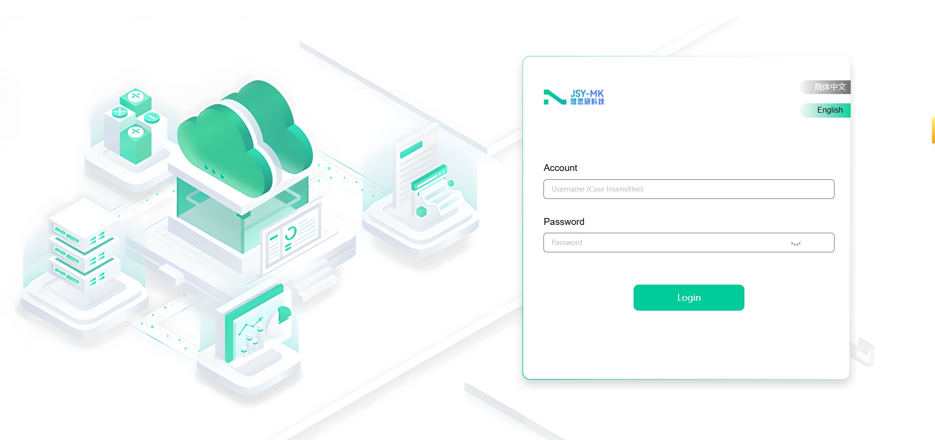
1.1.1 Log in
- Enter the IP address of the PDU in the URL address field of the web browser ( http://192.168.1.192 in the web page )
As shown

The default username and password for the super administrator is: " admin", then click Login. as shown in Figure 5.2.2:
Post time: Mar-19-2025