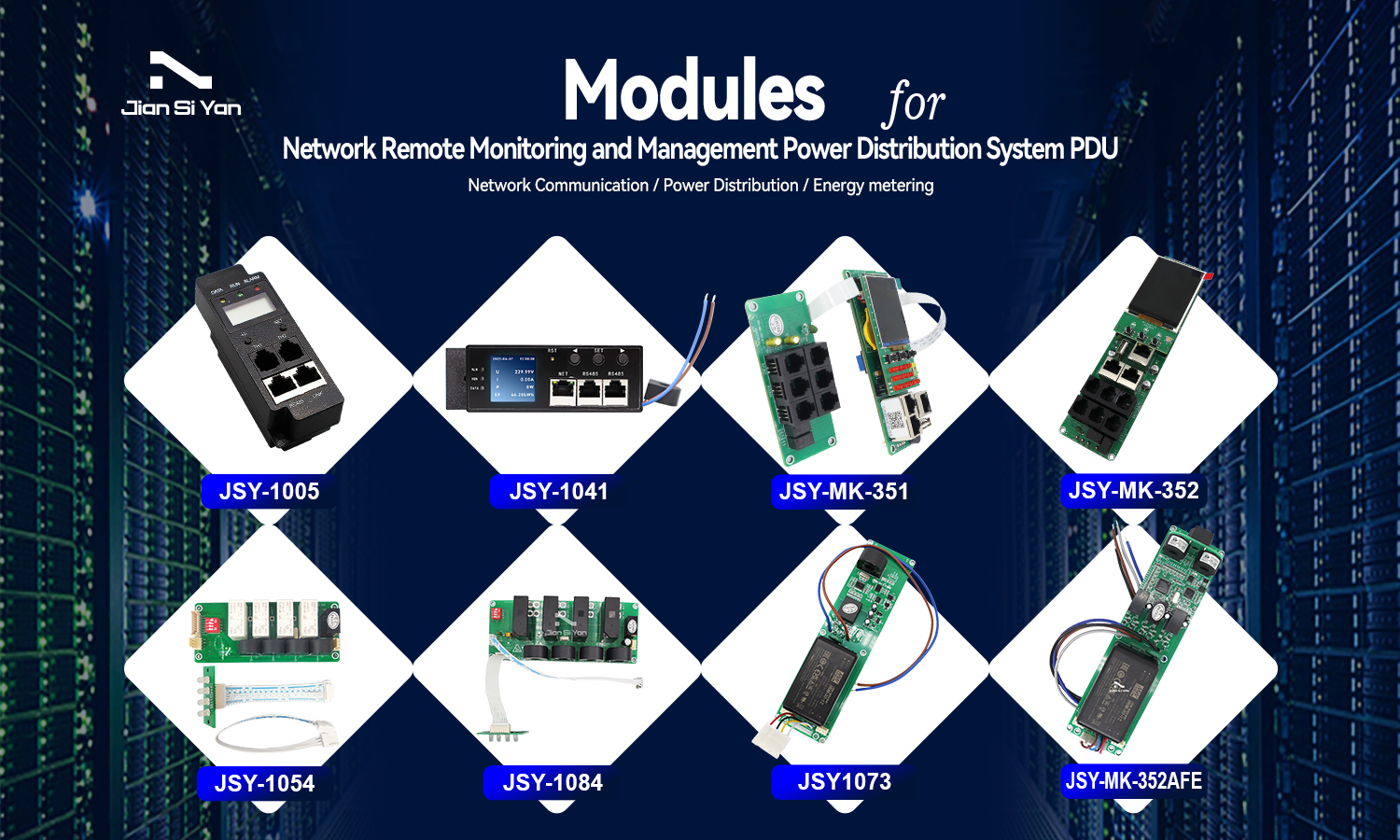
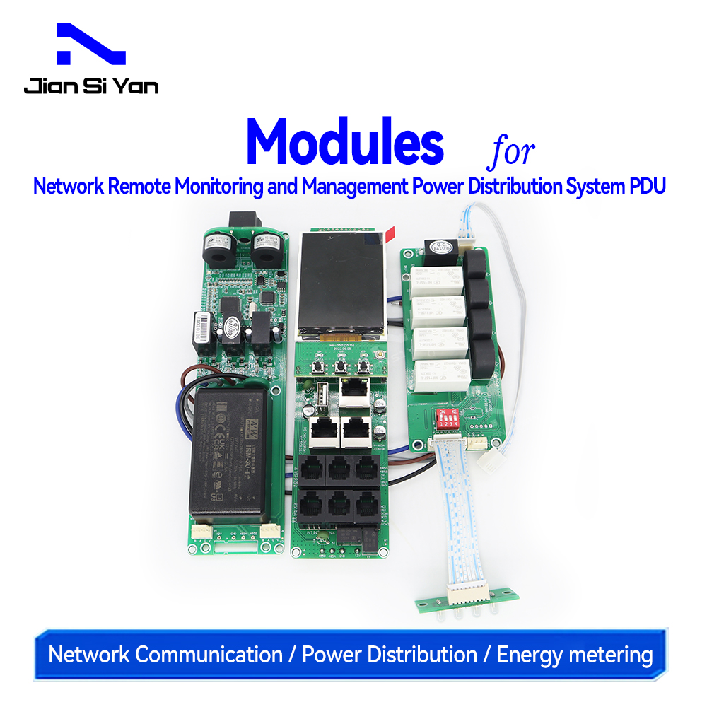
PDU Modules for Network Remote Monitoring and Management Power Distribution System

1 - Overview
The professional-grade network remote monitoring and management power distribution system is the latest scientific research achievement of our company after years of dedicated research in the field of power distribution technology. This product is carefully designed based on the development trend of future power distribution monitoring and management technology in the world, combined with the technical needs of modern data center application environments, using the latest core technology with completely independent intellectual property rights, and integrating network communication, power distribution, energy measurement and other technologies. The latest network remote monitoring and management power distributor.
2 - Technical parameters and indicators
2.1 Work indicators
1、Voltage measurement: AC110V, 220V, 380V, etc. optional.
2、Current measurement: 5A, 20A, 50A, 100A, 200A, 300A, 400A, 500A, etc. optional.
3、Frequency: 50/60Hz.
4、Power supply range: AC85V~265V (taken from phase A).
2.1 Measurement accuracy
Voltage, current, power: ±1.0%
2.2 Measurement indicators
Measuring range: 0.00kWh~999999.9kWh.
Measurement accuracy: Level 1 (active electric energy).
2.3 Operating environment
1、Working temperature range: -10~60℃.
2、Extreme operating temperature range: -20~70℃.
3、Storage and transportation limit temperature: -40~85℃.
4、Relative humidity: 5~95%, no condensation (at 40℃).
5、Altitude: 0~3000 meters.
6、Environment: A place without explosion, corrosive gas and conductive dust, and without significant shaking, vibration and impact.
2.4 Electromagnetic Compatibility
1、Static electricity immunity: contact discharge 4kV, air discharge 8kV
2、Electrical fast pulse group immunity: communication port 2kV, power port 4kV
3、Surge immunity: communication port 2kV, power port 4kV.
2.5 Socket opening and closing performance
1、Load resistance: 16A250VAC
2、Maximum switching voltage: 440VAC
3、Maximum switching current: 16A
4、Maximum switching power: 3000VA
5、Mechanical durability: 1x106 times
6、Electrical durability: 5000 times (16A, 250VAC, resistive load, room temperature, 1S on and 9S off) .

3 - The main function
3.1 Real-time monitoring function
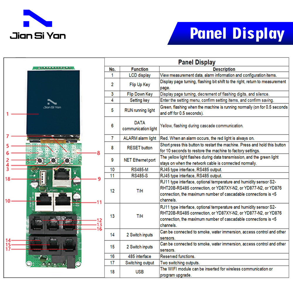
The monitored total load current, total voltage, total power, total electric energy, power factor, and the load current of each independent unit can be viewed through the LCD display interface and buttons: the content displayed on the LCD screen and each independent unit can be viewed on the web page. The unit's closed/open status, temperature/humidity sensor data and operating status, 4 switching inputs can be configured by customers, and two switching outputs.
3.2 Outlet unit control functions
1、When a close (close) command is received, the relay closes.
2、When receiving the disconnection (opening) command, the relay opens.
3、To control the opening and closing of multi-channel relays, you can set the sequential power-on delay, up to 6 seconds. (This means that when two or more channels are controlled continuously, after the action of the previous channel ends, you need to wait 6 seconds before the next channel starts to act.)
4、Each relay can be turned on at a scheduled time and date.
3.3 Initial state settings
The state of each socket unit when it is powered on is the state when it is powered off, which is a maintained state.
Note: The function of the holding state is that the relay state after power-on is the state before power-off. the function of the off-state is that the relay is in the off-state after power-on. the function of the closed state is that the relay is in the closed state after power-on.
3.4 Custom alarm
The total load current/voltage over-limit threshold can be customized, the load current over-limit threshold of each socket unit can be customized, and the temperature/humidity over-limit threshold can be customized.
3.5 Various alarm methods
The buzzer sounds. the backlight of the LCD screen is always on. An E-mail is sent to the system administrator. SNMP sends Trap alarm status information.
3.6 Unit current overload monitoring
Detect the load current of each outlet output unit. If the load current of an output unit exceeds the threshold setting, the device buzzer will sound and the LCD screen will automatically light up. If an alarm notification mailbox is set, alarm information will be sent to the mailbox. The current value of the socket output unit flashes on the LCD screen and can be queried by pressing the button. If the load current exceeds the threshold setting, the buzzer will sound an alarm. You can click the up/down button on the panel to silence it, and the alarm will not be blocked.
3.7 Master-slave (cascade) settings
Set the master and slave status in the web interface. Only as the master can read the slave information. There cannot be duplicate addresses in the cascade network, otherwise communication abnormalities will occur.

3.8 Interview method
Supports Web access, and can log in to access control through IE, Google, 360 and other browsers.
3.9 Upgrade function
Support software upgrade
3.10 Provide secondary development interface
SNMP(V1/V2c/V3) ,
3.11 Reset
Short press the RESET button to reset.
3.12 Protocols
HTTP、SNMP(V1/V2c/V3)、SNMP trap/walk/GET、Modbus、DHCP.IPv4/IPv6、DNS、SMTP、TCP、SNTP、ARP、UDP、ICMP/ICMPv6、Syslog.
4 - Use and operation

IPDU Product Network Functions Interface Show
Post time: Jul-24-2024


